

I decided that I will write a series on the concept of Modulation, and the best way to begin this series is by giving an introduction to what Modulation is and introducing a specific technique called Amplitude Modulation. I will take the first couple of posts explaining the theory portion, and then we will focus on the implementation aspect of what we learned.
Modulation
Modulation is when you change a characteristic of a carrier wave in proportion to the instant value of the message signal. Modulation plays a huge role in our lives such as through Wireless Communication, Remote Controlling, TV Broadcasting, etc.
There are two main categories of Modulation:
Continuous Wave Modulation
Pulse Modulation
In Continuous Wave Modulation, the carrier wave is sinusoidal, while in Pulse Modulation, the carrier wave is discrete.
Amplitude Modulation falls in the category of Continuous Wave Modulation. Before we move on, let’s define the difference between the message signal and the carrier signal.
The message signal carries the information you are attempting to transmit, it is like the “original” signal as it has the content you would like to convey. The carrier signal as I mentioned before is sinusoidal. It carries the modulated information received from the message signal.
What is Amplitude?
Before we start diving into the basic theory of Amplitude Modulation, we must know what Amplitude is.
Amplitude refers to how high the wave is, meaning the magnitude of the signal. When we look at it through a mathematical lens…
y = A * sinx
“A” represents the Amplitude.
Amplitude Modulation
Now let’s get into the theory of Amplitude Modulation.
This Modulation technique is when the maximum Amplitude of the carrier wave depends on the instant amplitude of the message signal. As you can tell, the definition of Amplitude and the technique itself are closely related, hence the name “Amplitude Modulation”. In simple terms, the modulated wave depends on the amplitude of the message signal.
I will explain this concept further using rough diagrams I hand-sketched. Keep in mind, that these are rough diagrams I am drawing out just to explain the concept, they will not follow the exact dimensions you would see digitally.
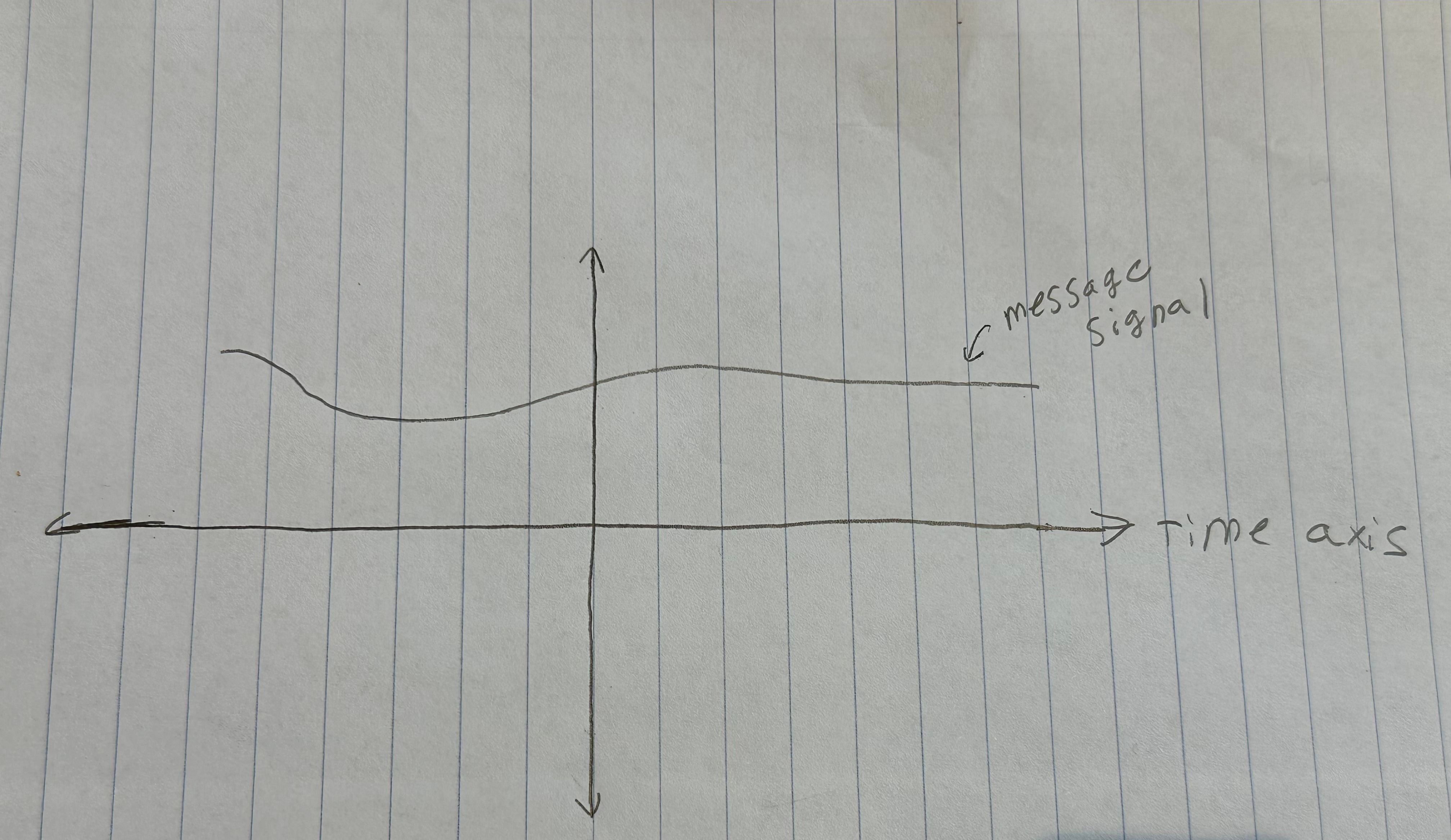
Let us say that we have a message signal such as the following:
Now if we want to get the carrier wave of this message signal using Amplitude Modulation, we have to develop it according to the instant amplitude of this message signal, like this:
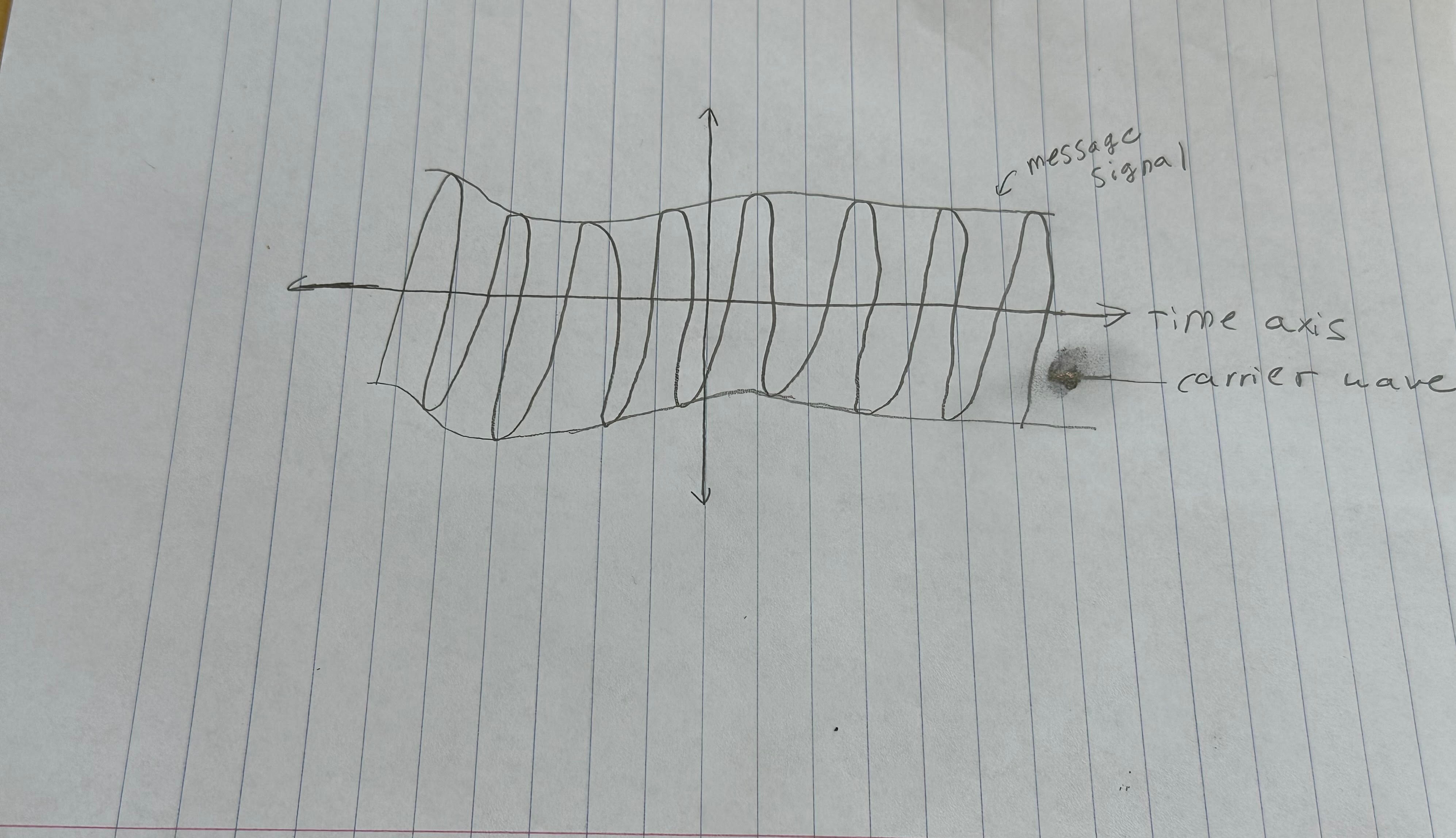
Again, this is a hand-drawn rough sketch, hence it will not be exact.
You can see that the carrier wave was developed off of the instant amplitude of the message wave, and this is how Amplitude Modulation works!
There are some important key terms to keep in mind when we look at the carrier wave.
Envelope
Lower Side Band
Upper Side Band
The envelope represents the changing amplitude of the carrier wave. The Lower Side Band represents the frequency below the carrier wave, meaning the Upper Side Band shows the frequency above the carrier wave.
This is the basic theory of Amplitude Modulation! Keep a look out for the next post as we will move on to the theory of another Modulation technique. Once we cover the basic theory of the different Modulation techniques, we will look at how to implement these different techniques through MATLAB.